What is Acoustic emission testing ? introduction of acoustic emission testing , application ,Equipment

What is Acoustic emission testing ?

Acoustic emission (AE) is the phenomenon of radiation of acoustic (elastic) waves in solids that occurs when a material undergoes irreversible changes in its internal structure, for example as a result of crack formation or plastic deformation due to aging, temperature gradients or external mechanical forces. In particular, AE is occurring during the processes of mechanical loading of materials and structures accompanied by structural changes that generate local sources of elastic waves. This results in small surface displacements of a material produced by elastic or stress waves generated when the accumulated elastic energy in a material or on its surface is released rapidly. The waves generated by sources of AE are of practical interest in structural health monitoring (SHM), quality control, system feedback, process monitoring and other fields. In SHM applications, AE is typically used to detect, locate and characterise damage.

The Acoustic Emission NDT technique is based on the detection and conversion of these high frequency elastic waves to electrical signals. This is accomplished by directly coupling piezoelectric transducers on the surface of the structure under test and loading the structure. Sensors are coupled to the structure by means of a fluid couplant and are secured with tape, adhesive bonds or magnetic hold downs. The output of each piezoelectric sensor (during structure loading) is amplified through a low-noise preamplifier, filtered to remove any extraneous noise and furthered processed by suitable electronic equipment.

Applications of acoustic emission testing

  • Laboratory & R&D studies
  • In field inspection
  • Structural integrity evaluation
  • Vessels testing [ambient, hot or cryogenic, metallic and FRP, spheres]
  • Tank bottom testing
  • Nuclear components inspection (valves, lift beams, steam lines)
  • Corrosion detection
  • Pipeline testing
  • Transformers testing (Partial Discharge)
  • Railroad tank car testing
  • Tube trailers & high pressure gas cylinders
  • Reactor & high energy piping testing
  • Aging aircraft evaluation
  • Advanced materials testing (composites, ceramics)
  • Production quality control
  • Rocket motor testing.

Acoustic Emission for Laboratory Testing

Acoustic Emission inspection is a powerful aid to materials testing and the study of deformation, fracture and corrosion. It gives an immediate indication of the response and behavior of a material under stress, intimately connected with strength, damage and failure. Acoustic Emission is used also for monitoring chemical reactions including corrosion process, liquid solid transformations, phase transformations.

 Acoustic Emission in field testing 

Many codes and standards exist for Acoustic Emission testing of vessels, from transportation gas cylinders and railroad tanks to thousands tons storage tanks. Because only active defects and deterioration produce Acoustic Emission no time is wasted on inactive defects which are not threatening structural integrity.

Global monitoring- 100% Inspection of the structure

A major advantage of Acoustic Emission inspection is that does not require access to the whole examination area. E.g. for covering a total area of a 16m-diameter sphere 30-40 sensors are needed. Thus, the cost of the test is significantly less than inspection with conventional NDT methods (for 100% inspection and scanning of the whole area). Identified problem areas can be inspected using conventional NDT methods.

Testing with insulation /high temperature processes

In cases of insulation, only small holes in insulation are required for sensors mounting, resulting in more cost savings. In cases of high temperature processes, wave-guides are used to guide the Acoustic Emission waves from the hot surface to the edge where the sensor is mounted. Finally, in large cryogenic vessels, permanent sensors are mounted under insulation for periodic inspection control.

On-line testing

As the method records defects in real time, it offers the possibility of on-line inspection, e.g. during hydrostatic testing. Other types of on-line stress application are introducing of gas into the upper vapor space, temperature control etc.

Rapid inspection

The actual Acoustic Emission test takes a matter of hours, and, in some cases, even less. There is no comparable technique which can provide 100% volumetric inspection.

Cost Reduction

The use of Acoustic Emission results in considerable reduction in plant maintenance costs, while increasing the available information about plant integrity. Plant downtime for inspection is also minimized.

Permanent recording of test

Acoustic Emission data are digitized and stored on a PC, providing permanent recording of the test to be used at any time for re-evaluation and post processing analysis.

Defect Location

When more that one sensors are used, Acoustic Emission source can be located and, thus, the defective area. Location is based on the wave propagation principles within the materials and is effectuated by measuring the signal’s arrival time to each sensor. By comparing the signal’s arrival time at different sensors, the flaw’s location can be defined through triangulation.
Linear location is used on long gas cylinders, planar (2-dimensional) location for thick walled and gas filled vessels, while 3-dimensional location is used for power transformers and concrete structures.

Equipment

Acoustic Emission Sensor Collage

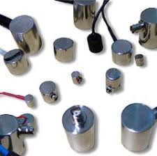
Acoustic emission testing can be performed in the field with portable instruments or in a stationary laboratory setting. Typically, systems contain a sensor, preamplifier, filter, and amplifier, along with measurement, display, and storage equipment (e.g. oscilloscopes, voltmeters, and personal computers). Acoustic emission sensors respond to dynamic motion that is caused by an AE event. This is achieved through transducers which convert mechanical movement into an electrical voltage signal. The transducer element in an AE sensor is almost always a piezoelectric crystal, which is commonly made from a ceramic such as lead zirconate titanate (PZT). Transducers are selected based on operating frequency, sensitivity and environmental characteristics, and are grouped into two classes: resonant and broadband. The majority of AE equipment is responsive to movement in its typical operating frequency range of 30 kHz to 1 MHz. For materials with high attenuation (e.g. plastic composites), lower frequencies may be used to better distinguish AE signals. The opposite holds true as well.


Ideally, the AE signal that reaches the mainframe will be free of background noise and electromagnetic interference. Unfortunately, this is not realistic. However, sensors and preamplifiers are designed to help eliminate unwanted signals. First, the preamplifier boosts the voltage to provide gain and cable drive capability. To minimize interference, a preamplifier is placed close to the transducer; in fact, many transducers today are equipped with integrated preamplifiers. Next, the signal is relayed to a bandpass filter for elimination of low frequencies (common to background noise) and high frequencies. Following completion of this process, the signal travels to the acoustic system mainframe and eventually to a computer or similar device for analysis and storage. Depending on noise conditions, further filtering or amplification at the mainframe may still be necessary.

Schematic Diagram of a Basic Four-channel Acoustic Emission Testing System

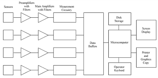
After passing the AE system mainframe, the signal comes to a detection/measurement circuit as shown in the figure directly above. Note that multiple-measurement circuits can be used in multiple sensor/channel systems for source location purposes (to be described later). At the measurement circuitry, the shape of the conditioned signal is compared with a threshold voltage value that has been programmed by the operator. Signals are either continuous (analogous to Gaussian, random noise with amplitudes varying according to the magnitude of the AE events) or burst-type. Each time the threshold voltage is exceeded, the measurement circuit releases a digital pulse. The first pulse is used to signify the beginning of a hit. (A hit is used to describe the AE event that is detected by a particular sensor. One AE event can cause a system with numerous channels to record multiple hits.) Pulses will continue to be generated while the signal exceeds the threshold voltage. Once this process has stopped for a predetermined amount of time, the hit is finished (as far as the circuitry is concerned). The data from the hit is then read into a microcomputer and the measurement circuit is reset.

NDT , Introduction of Ultrasonic testing ,History of Ultrasonic testing, ultrasonic testing in welding,pulse-echo,through-transmission,Advantages,Disadvantages

History of Ultrasonic testing .

On May 27, 1940, U.S. researcher Dr. Floyd Firestone of the University of Michigan applies for a U.S. invention patent for the first practical ultrasonic testing method. The patent is granted on April 21, 1942 as U.S. Patent No. 2,280,226, titled “Flaw Detecting Device and Measuring Instrument”. Extracts from the first two paragraphs of the patent for this entirely new nondestructive testing method succinctly describe the basics of such ultrasonic testing. “My invention pertains to a device for detecting the presence of inhomogeneities of density or elasticity in materials. For instance if a casting has a hole or a crack within it, my device allows the presence of the flaw to be detected and its position located, even though the flaw lies entirely within the casting and no portion of it extends out to the surface.The general principle of my device consists of sending high frequency vibrations into the part to be inspected, and the determination of the time intervals of arrival of the direct and reflected vibrations at one or more stations on the surface of the part.”

What is meant by ultrasonic testing?

Ultrasonic testing (UT) is a non-destructive test method that utilizes sound waves to detect cracks and defects in parts and materials. It can also be used to determine a material’s thickness, such as measuring the wall thickness of a pipe.

What is ultrasonic testing in welding?

Ultrasonic testing of welds. Ultrasonic testing technology is based on the ability of high-frequency oscillations (about 20,000 Hz) to propagate into the metal and be reflected from surface scratches, voids, and other discontinuities.relative size of the defect – through the amplitude of the reflected pulse.

How ultrasonic testing works ?

In ultrasonic testing, an ultrasound transducer connected to a diagnostic machine is passed over the object being inspected. The transducer is typically separated from the test object by a couplant (such as oil) or by water, as in immersion testing. However, when ultrasonic testing is conducted with an Electromagnetic Acoustic Transducer (EMAT) the use of couplant is not required.


There are two methods of receiving the ultrasound waveform: reflection and attenuation. 

reflection (or pulse-echo)

In reflection (or pulse-echo) mode, the transducer performs both the sending and the receiving of the pulsed waves as the “sound” is reflected back to the device. Reflected ultrasound comes from an interface, such as the back wall of the object or from an imperfection within the object. The diagnostic machine displays these results in the form of a signal with an amplitude representing the intensity of the reflection and the distance, representing the arrival time of the reflection. 

attenuation (or through-transmission)

In attenuation (or through-transmission) mode, a transmitter sends ultrasound through one surface, and a separate receiver detects the amount that has reached it on another surface after traveling through the medium. Imperfections or other conditions in the space between the transmitter and receiver reduce the amount of sound transmitted, thus revealing their presence. Using the couplant increases the efficiency of the process by reducing the losses in the ultrasonic wave energy due to separation between the surfaces.

Advantages

  1. High penetrating power, which allows the detection of flaws deep in the part.
  2. High sensitivity, permitting the detection of extremely small flaws.
  3. In many cases only one surface needs to be accessible.
  4. Greater accuracy than other nondestructive methods in determining the depth of internal flaws and the thickness of parts with parallel surfaces.
  5. Some capability of estimating the size, orientation, shape and nature of defects.
  6. Some capability of estimating the structure of alloys of components with different acoustic properties
  7. Non-hazardous to operations or to nearby personnel and has no effect on equipment and materials in the vicinity.
  8. Capable of portable or highly automated operation.
  9. Results are immediate. Hence on the spot decisions can be made.

Disadvantages

  1. Manual operation requires careful attention by experienced technicians. The transducers alert to both normal structure of some materials, tolerable anomalies of other specimens (both termed “noise”) and to faults therein severe enough to compromise specimen integrity. These signals must be distinguished by a skilled technician, possibly requiring follow up with other nondestructive testing methods.
  2. Extensive technical knowledge is required for the development of inspection procedures.
  3. Parts that are rough, irregular in shape, very small or thin, or not homogeneous are difficult to inspect.
  4. Surface must be prepared by cleaning and removing loose scale, paint, etc., although paint that is properly bonded to a surface need not be removed.
  5. Couplants are needed to provide effective transfer of ultrasonic wave energy between transducers and parts being inspected unless a non-contact technique is used. Non-contact techniques include Laser and Electro Magnetic Acoustic Transducers (EMAT).

NDT, Introduction of Dye penetrate testing , principle , Inspection steps,Advantages,Limitations

Introduction of Dye penetrants testing

History of Dye penetrants testing 

The oil and whiting method used in the railroad industry in the early 1900s was the first recognized use of the principles of penetrants to detect cracks. The oil and whiting method used an oil solvent for cleaning followed by the application of a whiting or chalk coating, which absorbed oil from the cracks revealing their locations. Soon a dye was added to the liquid. By the 1940s, fluorescent or visible dye was added to the oil used to penetrate test objects.

Dye penetrant inspection (DP), also called liquid penetrate inspection (LPI) or penetrant testing (PT), is a widely applied and low-cost inspection method used to check surface-breaking defects in all non-porous materials (metals, plastics, or ceramics).

The principle of liquid penetrant testing

The principle of liquid penetrant testing is that the liquid penetrant is drawn into the surface-breaking crack by capillary action and excess surface penetrant is then removed; a developer (typically a dry powder) is then applied to the surface, to draw out the penetrant in the crack and produce a surface indication.

Penetrant materials come in two basic types:

  • Type 1 – Fluorescent Penetrants : they contain a dye or several dyes that fluoresce when exposed to ultraviolet radiation. 
  • Type 2 – Visible Penetrants: they contain a red dye that provides high contrast against the white developer background.

Fluorescent penetrant systems are more sensitive than visible penetrant systems because the eye is drawn to the glow of the fluorescing indication. However, visible penetrants do not require a darkened area and an ultraviolet light in order to make an inspection.

Lipophilic emulsification systems are oil-based materials that are supplied in ready-to-use form.The hydrophilic emulsifier breaks up the penetrant into small quantities and prevents these pieces from recombining or reattaching to the surface of the part.

Inspection steps.

Below are the main steps of Liquid Penetrant Inspection:

1. Pre-cleaning:

The test surface is cleaned to remove any dirt, paint, oil, grease or any loose scale that could either keep penetrant out of a defect, or cause irrelevant or false indications. Cleaning methods may include solvents, alkaline cleaning steps, vapor degreasing, or media blasting. The end goal of this step is a clean surface where any defects present are open to the surface, dry, and free of contamination. Note that if media blasting is used, it may “work over” small discontinuities in the part, and an etching bath is recommended as a post-blasting treatment.

Application of the penetrant to a part in a ventilated test area.

2. Application of Penetrant:

The penetrant is then applied to the surface of the item being tested. The penetrant is usually a brilliant coloured mobile fluid with high wetting capability. The penetrant is allowed “dwell time” to soak into any flaws (generally 5 to 30 minutes). The dwell time mainly depends upon the penetrant being used, material being tested and the size of flaws sought. As expected, smaller flaws require a longer penetration time. Due to their incompatible nature one must be careful not to apply solvent-based penetrant to a surface which is to be inspected with a water-washable penetrant.

3. Excess Penetrant Removal:

The excess penetrant is then removed from the surface. The removal method is controlled by the type of penetrant used. Water-washable, solvent-removable, lipophilic post-emulsifiable, or hydrophilic post-emulsifiable are the common choices. Emulsifiers represent the highest sensitivity level, and chemically interact with the oily penetrant to make it removable with a water spray. When using solvent remover and lint-free cloth it is important to not spray the solvent on the test surface directly, because this can remove the penetrant from the flaws. If excess penetrant is not properly removed, once the developer is applied, it may leave a background in the developed area that can mask indications or defects. In addition, this may also produce false indications severely hindering the ability to do a proper inspection. Also, the removal of excessive penetrant is done towards one direction either vertically or horizontally as the case may be.

4. Application of Developer:

After excess penetrant has been removed, a white developer is applied to the sample. Several developer types are available, including: non-aqueous wet developer, dry powder, water-suspendable, and water-soluble. Choice of developer is governed by penetrant compatibility (one can’t use water-soluble or -suspendable developer with water-washable penetrant), and by inspection conditions. When using non-aqueous wet developer (NAWD) or dry powder, the sample must be dried prior to application, while soluble and suspendable developers are applied with the part still wet from the previous step. NAWD is commercially available in aerosol spray cans, and may employ acetone, isopropyl alcohol, or a propellant that is a combination of the two. Developer should form a semi-transparent, even coating on the surface.

The developer draws penetrant from defects out onto the surface to form a visible indication, commonly known as bleed-out. Any areas that bleed out can indicate the location, orientation and possible types of defects on the surface. Interpreting the results and characterizing defects from the indications found may require some training and/or experience [the indication size is not the actual size of the defect].

5. Inspection:

The inspector will use visible light with adequate intensity (100 foot-candles or 1100 lux is typical) for visible dye penetrant. Ultraviolet (UV-A) radiation of adequate intensity (1,000 micro-watts per centimeter squared is common), along with low ambient light levels (less than 2 foot-candles) for fluorescent penetrant examinations. Inspection of the test surface should take place after 10- to 30-minute development time, and is dependent on the penetrant and developer used. This time delay allows the blotting action to occur. The inspector may observe the sample for indication formation when using visible dye. It is also good practice to observe indications as they form because the characteristics of the bleed out are a significant part of interpretation characterization of flaws.

6. Post Cleaning:

The test surface is often cleaned after inspection and recording of defects, especially if post-inspection coating processes are scheduled.

Advantages

  • Simple to use and interpret
  • Relatively inexpensive
  • Portable and require no elaborate equipment
  • Work on all materials

Limitations

  • Only surface defect will be detected
  • Surface must be clean and dry
  • Rust or paint will mask defects

Introduction of Radiographic testing (NDT),History of radiographic testing,Advantages,Limitations

History of radiographic testing

  • The history of radiographic testing actually involves two beginnings. The first commenced with the discovery of x-Rays by Wilhelm Conrad Röntgen in 1895 and the second with the announcement by Marie Curie, in December of 1898, that the demonstrated the existence of a new radioactive material called “Radium”.

Radiographic testing in welding

  • Radiography or Radiographic Testing (RT) or industrial radiography, is a nondestructive testing (NDT) method of welding inspection or inspecting materials for hidden flaws by using the ability of short wavelength electromagnetic radiation (high energy photons) to penetrate various materials.

Principle of radiographic testing

  • It is based on the principle that radiation is absorbed and scattered as it passes through an object. If there are variations in thickness or density (e.g. due to defects) in an object, more or less radiation passes through and affects the film exposure. Flaws show up on the film, usually as dark areas.
  • RT makes use of X-rays or gamma rays. X-rays are produced by an X-ray tube, and gamma rays are produced by a radioactive isotope.
X ray tube
Delta camera used as industrial radiographic gamma source
  • The method is based on the same principle as medical radiography in a hospital. A piece of radiographic film is placed on the remote side of the material under inspection and radiation is then transmitted through from one side of the material to the remote side where the radiographic film is placed.
  • The radiographic film detects the radiation and measures the various quantities of radiation received over the entire surface of the film. This film is then processed under dark room conditions and the various degrees of radiation received by the film are imaged by the display of different degrees of black and white, this is termed the film density and is viewed on a special light emitting device.
  • Discontinuities in the material affect the amount of radiation being received by the film through that particular plane of the material. Qualified inspectors can interpret the resultant images and record the location and type of defect present in the material. Radiography can be used on most materials and product forms, e.g. welds, castings, composites etc.
  • Radiographic testing provides a permanent record in the form of a radiograph and provides a highly sensitive image of the internal structure of the material.
  • The amount of energy absorbed by the object depends on its thickness and density. Energy not absorbed by the object causes exposure of the radiographic film. These areas will be dark when the film is developed. Areas of the film exposed to less energy remain lighter. Therefore, areas of the object where the thickness has been changed by discontinuities, such as porosity or cracks, will appear as dark outlines on the film. Inclusions of low density, such as slag, will appear as dark areas on the film, while inclusions of high density, such as tungsten, will appear as light areas.
  • All discontinuities are detected by viewing the weld shape and variations in the density of the processed film. This permanent film record of weld quality is relatively easy to interpret if personnel are properly trained. Only qualified personnel should conduct radiography and radiographic interpretation because false readings can be expensive and can interfere seriously with productivity, and because invisible X-ray and gamma radiation can be hazardous.

X-ray Radiography

Advantages

  • Provides permanent record on film
  • Technique standardized
  • Reference standards available
  • Adjustable energy level gives high sensitivity
  • Fluoroscopy techniques available

Limitations

  • Trained technician needed
  • Radiation hazards
  • High cost of equipment
  • Power source needed

Gamma-ray Radiography

Advantages

  • Provides permanent record on film
  • Technique standardized
  • Reference standards available
  • Low initial cost
  • Portable, independent of power supply
  • Makes panoramic exposures

Limitations

  • Trained technician needed
  • Radiation hazards
  • Fixed energy levels per source
  • Source looses strength continuously
  • Generally lower sensitivity and definition than x-ray radiography

Introduction to Nondestructive Testing

Nondestructive testing

(NDT) has been defined as comprising those test methods which are used to examine an object, material or system without impairing its future usefulness. -Determine the integrity of a material, component or structure- or Definition of NDT Quantitatively measure- some characteristic of an object.

Characteristics of NDT

  • Tested parts are not damaged
  • Various tests can be performed on the same product
  • Does not affect the future usefulness – of the object or material.
  • Can be performed on parts that are in service
  • Low time consumption
  • Low cost

Some Uses of NDE Methods

  • Flaw Detection – and Evaluation
  • Leak Detection • Dimensional Measurements
  • Structure and Microstructure Characterization
  • Estimation of Mechanical Properties
  • Material Sorting and Chemical Composition Determination
  • To verify proper assembly
  • To inspect for in-service damage

When are NDE Methods Used?

  • There are NDE application at almost any stage in the production or life cycle of a component.
  • To ensure the quality right from raw material stage through fabrication and processing to preservice and in-service inspection.
  • NDT finds extensive applications for condition monitoring, residual life assessment

Principle of NDT

  • Energy source or medium used to probe the test object (such as X-rays in radiography)
  • Nature of the signals or signature resulting from interaction with the test object (attenuation of X-rays)
  • Means of detecting or sensing resulting signals (photo emulsion effect)
  • Method of indicating or recording signals (radiographic film)

Most Common NDT Methods

  1. Visual and optical  Testing (VT)
  2.  Liquid Penetrant Testing (PT)
  3.  Magnetic Particle Testing (MT)
  4.  Ultrasonic Testing (UT)
  5.  Eddy Current Testing / Electromagnetic Testing  (ET)
  6.  Radiography Testing (RT)
  7.  Acoustic emission Testing (AE)
  8.  Leak Testing (LT)
  9.  Neutron Radiographic testing (NR)
  10. Vibration Analysis Testing (VA)
  11. Infrared / Thermal Testing (IR)

Principle of NDT methods

  1. Vibration Analysis Testing (VA)-One of the most interesting and useful applications of shearographic interferometry is the detection, visualisation and measurement of the mechanical vibration of opaque objects.
  2. Visual and optical  testing (VT)- Used in maintenance of facilities, mean inspection of equipment and structures using either or all of raw human senses such as vision, hearing, touch and smell and/or any non-specialized inspection equipment.
  3.  Leak Testing (LT)-A leak test procedure is a quality control step to assure a device integrity, and is one-time nondestructive test.
  4. Acoustic emission Testing (AE)-Acoustic Emission analysis provides overall information on the physical condition and leakproofness of the tested object.
  5. Infrared / Thermal Testing (IR)-Aims at the detection of subsurface features (i.e. subsurface defects, anomalies, etc.), owing to temperature differences (DT) observed on the investigated surface during monitoring by an infrared camera.
  6.  Neutron Radiographic testing (NR)-  utilizes transmission of radiation to obtain visual information on the structure and/or inner processes of a given object.
  7. Radiography  Testing (RT) -Attenuation of Electromagnetic Radiation
  8. Ultrasonic Testing (UT) -Reflection, refraction, Diffraction, etc of high frequency sound wave.
  9. Magnetic particle Testing (MT) -Leakage of magnetic flux due to any discontinuity.
  10. Penetrant Testing (PT) -Capillary action  and blotting action of liquid penetrant.
  11. Eddy current Testing (ET) -Disturbance of electromagnetic induction.

CLASSIFICATION

  • Surface Methods: NDT methods which are suitable for the examination of surface only. –Visual Testing –Liquid Penetrant Testing
  • Subsurface Methods: Suitable for detecting surface as well as subsurface discontinuities. –Magnetic Particle Testing –Eddy Current Testing
  • Volumetric Methods: Suitable for the examination of whole volume of the object. –Ultrasonic Testing, – Radiography Testing –

Applications Inspection of Raw Products

  • Forgings
  • Castings Rolling etc.

Inspection Following Secondary Processing

  • Machining
  • Welding
  • Grinding
  • Heat treating
  • Plating

Inspection For In-Service Damage

  • Cracking
  • Corrosion
  • Erosion/Wear

Mechanical testing ,Tensile tests ,Toughness testing (Charpy, Izod) ,Macro testing ,Bend testing ,Fillet weld fracture testing

WHAT IS MECHANICAL TESTING ?

     ⦁ The ultimate means by which the mechanical strength and toughness of a prepared test object  can be determined by subjecting it to mechanical forces beyond the limits of its own mechanical  resistance.

Destructive testing of welded joints are usually carried out to:

     ⦁ Approve welding procedures
     ⦁ Approve welders
     ⦁ Production quality control

The following mechanical tests have units and are termed quantitative tests

     ⦁ Tensile tests : Tensile test is performed on welded test specimen as part of the weld procedure  (WPS / WPQR) qualification, welder qualification, weld performance qualification and Production weld qualification.

     ⦁ Toughness testing (Charpy, Izod) : Both Charpy and Izod impact testing are popular methods of determining impact strength, or toughness, of a material. In other words, these tests measure the total amount of energy that a material is able to absorb. This energy absorption is directly related to the brittleness of the material.

The following mechanical tests have no units and are termed qualitative tests

      ⦁Macro testing : Macro examination is the procedure in which a specimen is etched and evaluated macro-structurally at low magnifications, typically x10 or lower. Macro examination is a frequently used technique for evaluating steel products such as billets, bars, blooms, and forgings.

      ⦁Bend testing : The bend test is a simple and inexpensive qualitative test that can be used to evaluate both the ductility and soundness of a material. The bend test uses a coupon that is bent in three point bending to a specified angle.

      ⦁Fillet weld fracture testing :The fillet weld break test / fracture test  is a mechanical testing process for examining the root penetration in a destructive manner. While the macro-etch test provides penetration depth of the specimen in a given area, the fillet weld break test examines the root penetration for the entirety of the specimen. The test includes the potential failure points of the weld which are the stop and restart of the weld

What is an ASNT NDT Level 3 ?

An ASNT NDT Level 3 is an individual who assumes the title of NDT Level 3 , in part, through a screening process offered by the American Society for Nondestructive Testing under the scope of the ASNT NDT Level 3 Certification program. 

The program provide an independent review of a candidate’s credential,  followed by the satisfactory completion of two or more comprehensive examinations.

The mandatory basic Examinations addresses administrative and general technology knowledge issues,  while the method examinations address an in depth knowledge of the theory and practices of eleven Nondestructive testing methods. 

The society provide the examinations service for aspiring ASNT NDT Level 3 personnel four times a year at various locations throughout the United States.

Examinations are also offered in foreign location on an as-needed basis