NDT , Introduction of Ultrasonic testing ,History of Ultrasonic testing, ultrasonic testing in welding,pulse-echo,through-transmission,Advantages,Disadvantages

History of Ultrasonic testing .

On May 27, 1940, U.S. researcher Dr. Floyd Firestone of the University of Michigan applies for a U.S. invention patent for the first practical ultrasonic testing method. The patent is granted on April 21, 1942 as U.S. Patent No. 2,280,226, titled “Flaw Detecting Device and Measuring Instrument”. Extracts from the first two paragraphs of the patent for this entirely new nondestructive testing method succinctly describe the basics of such ultrasonic testing. “My invention pertains to a device for detecting the presence of inhomogeneities of density or elasticity in materials. For instance if a casting has a hole or a crack within it, my device allows the presence of the flaw to be detected and its position located, even though the flaw lies entirely within the casting and no portion of it extends out to the surface.The general principle of my device consists of sending high frequency vibrations into the part to be inspected, and the determination of the time intervals of arrival of the direct and reflected vibrations at one or more stations on the surface of the part.”

What is meant by ultrasonic testing?

Ultrasonic testing (UT) is a non-destructive test method that utilizes sound waves to detect cracks and defects in parts and materials. It can also be used to determine a material’s thickness, such as measuring the wall thickness of a pipe.

What is ultrasonic testing in welding?

Ultrasonic testing of welds. Ultrasonic testing technology is based on the ability of high-frequency oscillations (about 20,000 Hz) to propagate into the metal and be reflected from surface scratches, voids, and other discontinuities.relative size of the defect – through the amplitude of the reflected pulse.

How ultrasonic testing works ?

In ultrasonic testing, an ultrasound transducer connected to a diagnostic machine is passed over the object being inspected. The transducer is typically separated from the test object by a couplant (such as oil) or by water, as in immersion testing. However, when ultrasonic testing is conducted with an Electromagnetic Acoustic Transducer (EMAT) the use of couplant is not required.


There are two methods of receiving the ultrasound waveform: reflection and attenuation. 

reflection (or pulse-echo)

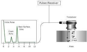
In reflection (or pulse-echo) mode, the transducer performs both the sending and the receiving of the pulsed waves as the “sound” is reflected back to the device. Reflected ultrasound comes from an interface, such as the back wall of the object or from an imperfection within the object. The diagnostic machine displays these results in the form of a signal with an amplitude representing the intensity of the reflection and the distance, representing the arrival time of the reflection. 

attenuation (or through-transmission)

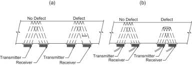
In attenuation (or through-transmission) mode, a transmitter sends ultrasound through one surface, and a separate receiver detects the amount that has reached it on another surface after traveling through the medium. Imperfections or other conditions in the space between the transmitter and receiver reduce the amount of sound transmitted, thus revealing their presence. Using the couplant increases the efficiency of the process by reducing the losses in the ultrasonic wave energy due to separation between the surfaces.

Advantages

  1. High penetrating power, which allows the detection of flaws deep in the part.
  2. High sensitivity, permitting the detection of extremely small flaws.
  3. In many cases only one surface needs to be accessible.
  4. Greater accuracy than other nondestructive methods in determining the depth of internal flaws and the thickness of parts with parallel surfaces.
  5. Some capability of estimating the size, orientation, shape and nature of defects.
  6. Some capability of estimating the structure of alloys of components with different acoustic properties
  7. Non-hazardous to operations or to nearby personnel and has no effect on equipment and materials in the vicinity.
  8. Capable of portable or highly automated operation.
  9. Results are immediate. Hence on the spot decisions can be made.

Disadvantages

  1. Manual operation requires careful attention by experienced technicians. The transducers alert to both normal structure of some materials, tolerable anomalies of other specimens (both termed “noise”) and to faults therein severe enough to compromise specimen integrity. These signals must be distinguished by a skilled technician, possibly requiring follow up with other nondestructive testing methods.
  2. Extensive technical knowledge is required for the development of inspection procedures.
  3. Parts that are rough, irregular in shape, very small or thin, or not homogeneous are difficult to inspect.
  4. Surface must be prepared by cleaning and removing loose scale, paint, etc., although paint that is properly bonded to a surface need not be removed.
  5. Couplants are needed to provide effective transfer of ultrasonic wave energy between transducers and parts being inspected unless a non-contact technique is used. Non-contact techniques include Laser and Electro Magnetic Acoustic Transducers (EMAT).

Introduction of Radiographic testing (NDT),History of radiographic testing,Advantages,Limitations

History of radiographic testing

  • The history of radiographic testing actually involves two beginnings. The first commenced with the discovery of x-Rays by Wilhelm Conrad Röntgen in 1895 and the second with the announcement by Marie Curie, in December of 1898, that the demonstrated the existence of a new radioactive material called “Radium”.

Radiographic testing in welding

  • Radiography or Radiographic Testing (RT) or industrial radiography, is a nondestructive testing (NDT) method of welding inspection or inspecting materials for hidden flaws by using the ability of short wavelength electromagnetic radiation (high energy photons) to penetrate various materials.

Principle of radiographic testing

  • It is based on the principle that radiation is absorbed and scattered as it passes through an object. If there are variations in thickness or density (e.g. due to defects) in an object, more or less radiation passes through and affects the film exposure. Flaws show up on the film, usually as dark areas.
  • RT makes use of X-rays or gamma rays. X-rays are produced by an X-ray tube, and gamma rays are produced by a radioactive isotope.
X ray tube
Delta camera used as industrial radiographic gamma source
  • The method is based on the same principle as medical radiography in a hospital. A piece of radiographic film is placed on the remote side of the material under inspection and radiation is then transmitted through from one side of the material to the remote side where the radiographic film is placed.
  • The radiographic film detects the radiation and measures the various quantities of radiation received over the entire surface of the film. This film is then processed under dark room conditions and the various degrees of radiation received by the film are imaged by the display of different degrees of black and white, this is termed the film density and is viewed on a special light emitting device.
  • Discontinuities in the material affect the amount of radiation being received by the film through that particular plane of the material. Qualified inspectors can interpret the resultant images and record the location and type of defect present in the material. Radiography can be used on most materials and product forms, e.g. welds, castings, composites etc.
  • Radiographic testing provides a permanent record in the form of a radiograph and provides a highly sensitive image of the internal structure of the material.
  • The amount of energy absorbed by the object depends on its thickness and density. Energy not absorbed by the object causes exposure of the radiographic film. These areas will be dark when the film is developed. Areas of the film exposed to less energy remain lighter. Therefore, areas of the object where the thickness has been changed by discontinuities, such as porosity or cracks, will appear as dark outlines on the film. Inclusions of low density, such as slag, will appear as dark areas on the film, while inclusions of high density, such as tungsten, will appear as light areas.
  • All discontinuities are detected by viewing the weld shape and variations in the density of the processed film. This permanent film record of weld quality is relatively easy to interpret if personnel are properly trained. Only qualified personnel should conduct radiography and radiographic interpretation because false readings can be expensive and can interfere seriously with productivity, and because invisible X-ray and gamma radiation can be hazardous.

X-ray Radiography

Advantages

  • Provides permanent record on film
  • Technique standardized
  • Reference standards available
  • Adjustable energy level gives high sensitivity
  • Fluoroscopy techniques available

Limitations

  • Trained technician needed
  • Radiation hazards
  • High cost of equipment
  • Power source needed

Gamma-ray Radiography

Advantages

  • Provides permanent record on film
  • Technique standardized
  • Reference standards available
  • Low initial cost
  • Portable, independent of power supply
  • Makes panoramic exposures

Limitations

  • Trained technician needed
  • Radiation hazards
  • Fixed energy levels per source
  • Source looses strength continuously
  • Generally lower sensitivity and definition than x-ray radiography

Mechanical testing ,Tensile tests ,Toughness testing (Charpy, Izod) ,Macro testing ,Bend testing ,Fillet weld fracture testing

WHAT IS MECHANICAL TESTING ?

     ⦁ The ultimate means by which the mechanical strength and toughness of a prepared test object  can be determined by subjecting it to mechanical forces beyond the limits of its own mechanical  resistance.

Destructive testing of welded joints are usually carried out to:

     ⦁ Approve welding procedures
     ⦁ Approve welders
     ⦁ Production quality control

The following mechanical tests have units and are termed quantitative tests

     ⦁ Tensile tests : Tensile test is performed on welded test specimen as part of the weld procedure  (WPS / WPQR) qualification, welder qualification, weld performance qualification and Production weld qualification.

     ⦁ Toughness testing (Charpy, Izod) : Both Charpy and Izod impact testing are popular methods of determining impact strength, or toughness, of a material. In other words, these tests measure the total amount of energy that a material is able to absorb. This energy absorption is directly related to the brittleness of the material.

The following mechanical tests have no units and are termed qualitative tests

      ⦁Macro testing : Macro examination is the procedure in which a specimen is etched and evaluated macro-structurally at low magnifications, typically x10 or lower. Macro examination is a frequently used technique for evaluating steel products such as billets, bars, blooms, and forgings.

      ⦁Bend testing : The bend test is a simple and inexpensive qualitative test that can be used to evaluate both the ductility and soundness of a material. The bend test uses a coupon that is bent in three point bending to a specified angle.

      ⦁Fillet weld fracture testing :The fillet weld break test / fracture test  is a mechanical testing process for examining the root penetration in a destructive manner. While the macro-etch test provides penetration depth of the specimen in a given area, the fillet weld break test examines the root penetration for the entirety of the specimen. The test includes the potential failure points of the weld which are the stop and restart of the weld